Bloom特效可以将周围将亮的区域扩散到周围的区域中,造成一种朦胧的效果。
using UnityEngine;

public class bloom : MonoBehaviour {

    public Material mat;

    [Range(0, 4)]
    public int iterations = 3; //高斯模糊处理次数

    [Range(0.2f,3.0f)]
    public float blurSpread = 0.6f; //模糊程度

    [Range(1, 8)]
    public int downSample = 2;

    [Range(0.0f, 4.0f)] //亮度阔值,一般不会超过1,但开启HDR的话会有更高的精度
    public float luminanceThreshold = 0.6f;

    private void OnRenderImage(RenderTexture source, RenderTexture destination)
    {
        if (mat != null)
        {
            mat.SetFloat("_LuminanceThreshold", luminanceThreshold);
            int w = source.width / downSample;
            int h = source.height / downSample;

            RenderTexture buffer0 = RenderTexture.GetTemporary(w, h, 0);
            buffer0.filterMode = FilterMode.Bilinear;
            Graphics.Blit(source, buffer0, mat, 0);

            //将光亮图高斯模糊,扩散到周围
            for (int i = 0; i < iterations; i++)
            {
                mat.SetFloat("_BlurSize", 1.0f + i * blurSpread);
                RenderTexture buffer1 = RenderTexture.GetTemporary(w, h, 0);
                Graphics.Blit(buffer0, buffer1, mat, 1);

                RenderTexture.ReleaseTemporary(buffer0);
                buffer0 = buffer1;
                buffer1 = RenderTexture.GetTemporary(w, h, 0);

                Graphics.Blit(buffer0, buffer1, mat, 2);
                RenderTexture.ReleaseTemporary(buffer0);
                buffer0 = buffer1;
            }

            mat.SetTexture("_Bloom", buffer0);
            Graphics.Blit(source, destination, mat, 3);
            RenderTexture.ReleaseTemporary(buffer0);
        }
        else
        {
            Graphics.Blit(source, destination);
        }
    }
}
Shader "Unlit/bloom"
{
Properties
{
_MainTex ("Texture", 2D) = "white" {}
_Bloom("Bloom",2D) = "black"{}
_LuminanceThreshold("Luminance Threshold",Float) = 0.5
_BlurSize("Blur Size",Float) = 1.0
}
SubShader
{
Tags { "RenderType"="Opaque" }
LOD 100
CGINCLUDE
#include "UnityCG.cginc"
struct v2f
{
float2 uv : TEXCOORD0;
float4 vertex : SV_POSITION;
};
sampler2D _MainTex;
float4 _MainTex_TexelSize;
sampler2D _Bloom;
float _LuminanceThreshold;
float _BlurSize;
v2f vertExtractBright(appdata_img v)
{
v2f o;
o.vertex = UnityObjectToClipPos(v.vertex);
o.uv = v.texcoord;
return o;
}
//光度贴图的取样,亮度超过阔值的才有值
fixed4 fragExtractBright(v2f i) : SV_Target
{
fixed4 c = tex2D(_MainTex,i.uv);
fixed val = clamp(Luminance(c) - _LuminanceThreshold, 0.0, 1.0);
return c * val;
}
struct v2fBloom
{
float4 pos : SV_POSITION;
half4 uv :TEXCOORD0;
};
v2fBloom vertBloom(appdata_img v)
{
v2fBloom o;
o.pos = UnityObjectToClipPos(v.vertex);
o.uv.xy = v.texcoord;
o.uv.zw = v.texcoord;
//平台差异化处理
#if UNITY_UV_STARTS_AT_TOP
if (_MainTex_TexelSize.y < 0.0)
o.uv.w = 1.0 - o.uv.w;
#endif
return o;
}
fixed4 fragBloom(v2fBloom i) :SV_Target
{
//为较亮区域添加亮度
return tex2D(_MainTex,i.uv.xy) + tex2D(_Bloom,i.uv.zw);
}
ENDCG
ZTest Always Cull Off ZWrite Off
//得到较亮区域贴图
Pass
{
CGPROGRAM
#pragma vertex vertExtractBright
#pragma fragment fragExtractBright
ENDCG
}
//高斯模糊处理,扩散到周围
UsePass "Unlit/gsMohu/GAUSSING_BLUR_VERTICAL" //上次通过Name
UsePass "Unlit/gsMohu/GAUSSING_BLUR_GORIZONTAL"
//叠加,较亮区域
Pass
{
CGPROGRAM
#pragma vertex vertBloom
#pragma fragment fragBloom
ENDCG
}
}
Fallback Off
}UsePass使用的是 “高斯模糊”中使用NAME命名好的Pass,达到重用的目的


OpenGL和DirectX使用的是不同的屏幕空间坐标,在水平方向是相同的,但是在竖直方向是反过来的。在渲染到屏幕上或则渲染到RenderTexture上时,Unity都会为我们做了相应的翻转处理,当在DirectX平台上使用了渲染到纹理上时,Unity会翻转屏幕图像纹理。但是如果渲染到RenderTexture并开启了抗锯齿时,Unity是不会帮我们做处理的,我们需要自行的将y翻转过来。
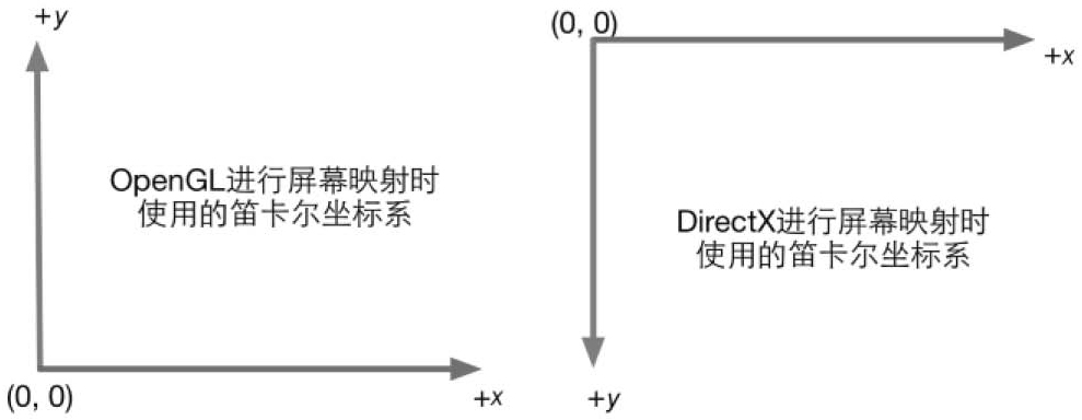
//自行反转操作
#if UNITY_UV_STARTS_AT_TOP
	if (_MainTex_TexelSize.y < 0.0)
		o.uv.w = 1.0 - o.uv.w;
#endif
using UnityEngine;

public class Mohua : MonoBehaviour {

    public Material mat;

    [Range(0, 4)]
    public int iterations = 3; //处理次数,越多次越模糊

    [Range(0.2f, 3.0f)]
    public float blurSpread = 0.6f;  //模糊程度

    [Range(1, 8)]
    public int downSample = 2; //取样缩放

    private void OnRenderImage(RenderTexture source, RenderTexture destination)
    {
        if (mat != null)
        {
            int rtW = source.width / downSample;
            int rtH = source.height / downSample;

            RenderTexture buffer0 = RenderTexture.GetTemporary(rtW, rtH, 0);
            buffer0.filterMode = FilterMode.Bilinear;

            Graphics.Blit(source, buffer0);

            for (int i = 0; i < iterations; i++)//处理的次数
            {
                mat.SetFloat("_BlurSize", 1.0f + i * blurSpread);
                RenderTexture buffer1 = RenderTexture.GetTemporary(rtW, rtH, 0);
                Graphics.Blit(buffer0, buffer1, mat, 0);//使用第一个pass做垂直方向的处理

                RenderTexture.ReleaseTemporary(buffer0);

                buffer0 = buffer1;
                buffer1 = RenderTexture.GetTemporary(rtW, rtH, 0);
                Graphics.Blit(buffer0, buffer1, mat, 1); //使用第二个pass做水平方向的处理

                RenderTexture.ReleaseTemporary(buffer0);
                buffer0 = buffer1;
            }

            Graphics.Blit(buffer0, destination);//显示处理后的图像
            RenderTexture.ReleaseTemporary(buffer0);
        }
        else
        {
            Graphics.Blit(source, destination);
        }
    }
}
Shader "Unlit/gsMohu"
{
Properties
{
_MainTex ("Texture", 2D) = "white" {}
_BlurSize ("Blur Size",Float) = 1.0
}
SubShader
{
Tags { "RenderType"="Opaque" }
LOD 100
CGINCLUDE //声明一块公用的
#include "UnityCG.cginc"
struct v2f
{
float2 uv[5] : TEXCOORD0;
float4 vertex : SV_POSITION;
};
sampler2D _MainTex;
half4 _MainTex_TexelSize;
float _BlurSize;
v2f vertBlurVertical (appdata_img v)
{
v2f o;
o.vertex = UnityObjectToClipPos(v.vertex);
half2 uv = v.texcoord;
//竖直方向的5个点取样,_BlurSize越大,取样的间距越大,模糊就越大
o.uv[0] = uv;
o.uv[1] = uv + float2(0.0, _MainTex_TexelSize.y * 1.0) * _BlurSize;
o.uv[2] = uv - float2(0.0, _MainTex_TexelSize.y * 1.0) * _BlurSize;
o.uv[3] = uv + float2(0.0, _MainTex_TexelSize.y * 2.0) * _BlurSize;
o.uv[4] = uv - float2(0.0, _MainTex_TexelSize.y * 2.0) * _BlurSize;
return o;
}
v2f vertBlurHorizontal(appdata_img v)
{
v2f o;
o.vertex = UnityObjectToClipPos(v.vertex);
half2 uv = v.texcoord;
//水平方向的5个点取样
o.uv[0] = uv;
o.uv[1] = uv + float2(0.0, _MainTex_TexelSize.x * 1.0) * _BlurSize;
o.uv[2] = uv - float2(0.0, _MainTex_TexelSize.x * 1.0) * _BlurSize;
o.uv[3] = uv + float2(0.0, _MainTex_TexelSize.x * 2.0) * _BlurSize;
o.uv[4] = uv - float2(0.0, _MainTex_TexelSize.x * 2.0) * _BlurSize;
return o;
}
fixed4 frag(v2f i) : SV_Target
{
float weight[3] = {0.4026,0.2442,0.0545}; //根据高斯方程计算处理啊的,标准方差为1,每个值相加为1
fixed3 sum = tex2D(_MainTex, i.uv[0]).rgb * weight[0];
for (int it = 1; it < 3; it++)
{
sum += tex2D(_MainTex, i.uv[it * 2 - 1]).rgb * weight[it];
sum += tex2D(_MainTex, i.uv[it * 2]).rgb * weight[it];
}
return fixed4(sum, 1.0);
}
ENDCG
ZTest Always Cull Off ZWrite Off
Pass
{
NAME "GAUSSING_BLUR_VERTICAL" //为Pass命名,方便在其他SubShader中重用
CGPROGRAM
#pragma vertex vertBlurVertical
#pragma fragment frag
ENDCG
}
Pass
{
NAME "GAUSSING_BLUR_GORIZONTAL"
CGPROGRAM
#pragma vertex vertBlurHorizontal
#pragma fragment frag
ENDCG
}
}
FallBack "Diffuse"
}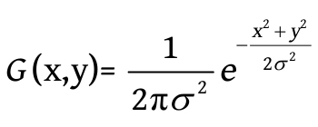
高斯方程


单通道 单独处理单个方向 传offset参数
Shader "PostEffect/SeparableGlassBlur" {
   Properties {
      _MainTex ("Base (RGB)", 2D) = "" {}
   }

   HLSLINCLUDE

   #include "Packages/com.unity.render-pipelines.universal/ShaderLibrary/Core.hlsl"

   struct appdata_img {
      float4 vertex:POSITION;
      float2 texcoord:TEXCOORD0;
   };
   struct v2f {
      float4 pos : POSITION;
      float2 uv : TEXCOORD0;

      float4 uv01 : TEXCOORD1;
      float4 uv23 : TEXCOORD2;
      float4 uv45 : TEXCOORD3;
   };

   float4 offsets;

   sampler2D _MainTex;

   v2f vert (appdata_img v) {
      v2f o;
      VertexPositionInputs vertexInput = GetVertexPositionInputs(v.vertex.xyz);
      o.pos = vertexInput.positionCS;
      o.uv.xy = v.texcoord.xy;

      o.uv01 =  v.texcoord.xyxy + offsets.xyxy * float4(1,1, -1,-1);
      o.uv23 =  v.texcoord.xyxy + offsets.xyxy * float4(1,1, -1,-1) * 2.0;
      o.uv45 =  v.texcoord.xyxy + offsets.xyxy * float4(1,1, -1,-1) * 3.0;
      return o;
   }

   half4 frag (v2f i) : COLOR {
      half4 color = float4 (0,0,0,0);

      color += 0.40 * tex2D (_MainTex, i.uv);
      color += 0.15 * tex2D (_MainTex, i.uv01.xy);
      color += 0.15 * tex2D (_MainTex, i.uv01.zw);
      color += 0.10 * tex2D (_MainTex, i.uv23.xy);
      color += 0.10 * tex2D (_MainTex, i.uv23.zw);
      color += 0.05 * tex2D (_MainTex, i.uv45.xy);
      color += 0.05 * tex2D (_MainTex, i.uv45.zw);

      return color;
   }

   ENDHLSL

Subshader {
 Pass {
     ZTest Always Cull Off ZWrite Off

      HLSLPROGRAM
      #pragma vertex vert
      #pragma fragment frag
      ENDHLSL
  }
}

}Shader "Unlit/mohu"
{
Properties
{
_MainTex ("Texture", 2D) = "white" {}
}
SubShader
{
Tags { "RenderType"="Opaque" }
LOD 100
Pass
{
ZTest Always Cull Off ZWrite Off
CGPROGRAM
#pragma vertex vert
#pragma fragment frag
#include "UnityCG.cginc"
struct v2f
{
float2 uv[9] : TEXCOORD0;
float4 vertex : SV_POSITION;
};
sampler2D _MainTex;
float4 _MainTex_TexelSize;//纹理每个纹素的大小,例如512*512,那就是1/512
v2f vert (appdata_img v)
{
v2f o;
o.vertex = UnityObjectToClipPos(v.vertex);
half2 uv = v.texcoord;
//计算出当前像素附近的8个像素点,在顶点处理后会经过插值到片元(线性操作),不影响
o.uv[0] = uv + _MainTex_TexelSize.xy * half2(-1, -1);
o.uv[1] = uv + _MainTex_TexelSize.xy * half2(0, -1);
o.uv[2] = uv + _MainTex_TexelSize.xy * half2(1, -1);
o.uv[3] = uv + _MainTex_TexelSize.xy * half2(-1, 0);
o.uv[4] = uv + _MainTex_TexelSize.xy * half2(0, 0);
o.uv[5] = uv + _MainTex_TexelSize.xy * half2(1, 0);
o.uv[6] = uv + _MainTex_TexelSize.xy * half2(-1, 1);
o.uv[7] = uv + _MainTex_TexelSize.xy * half2(0, 1);
o.uv[8] = uv + _MainTex_TexelSize.xy * half2(1, 1);
return o;
}
fixed4 frag (v2f i) : SV_Target
{
//卷积核,取周围颜色的平均值作为新的颜色值 1/9
const half Gx[9] = { 0.11111, 0.11111, 0.11111,
0.11111, 0.11111, 0.11111,
0.11111, 0.11111, 0.11111 };
fixed4 texColor;
fixed4 col = 0;
for (int it = 0; it < 9; it++)
{
texColor = tex2D(_MainTex, i.uv[it]);
col += texColor * Gx[it];
}
return col;
}
ENDCG
}
}
Fallback Off
}

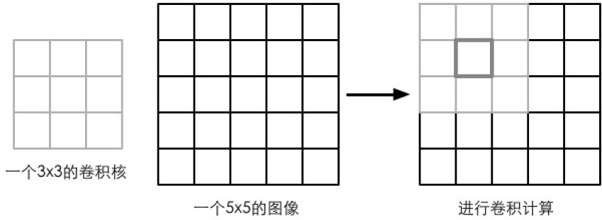
卷积操作就是使用一个卷积核对一张图像中的每个像素进行一系列操作。卷积核通常是一个四方形网格结构(2*2,3*3),每个方格都有一个权重值。当对图像的某个像素进行卷积时,我们会把卷积的中心放置在改像素上,翻转核之后在依次计算核中每个元素和其覆盖的图像像素值的乘积并求和,得到的结果就是该位置的新像素值。(可以用来实现图像模糊,边缘检测等)
using UnityEngine;

public class Bianyuan : MonoBehaviour
{
    public Material mat;

    public Color edgeColor = Color.black; //描边的颜色

    private void OnRenderImage(RenderTexture source, RenderTexture destination)
    {
        if (mat != null)
        {
            mat.SetColor("_EdgeColor", edgeColor);

            Graphics.Blit(source, destination, mat);
        }
    }
}
Shader "Unlit/bianyuan"
{
Properties
{
_MainTex ("Texture", 2D) = "white" {}
_EdgeColor("Edge Color",Color) = (0,0,0,1)
}
SubShader
{
Tags { "RenderType"="Opaque" }
LOD 100
Pass
{
ZTest Always Cull Off ZWrite Off
CGPROGRAM
#pragma vertex vert
#pragma fragment frag
#include "UnityCG.cginc"
struct v2f
{
float2 uv[9] : TEXCOORD0;
float4 vertex : SV_POSITION;
};
sampler2D _MainTex;
float4 _MainTex_TexelSize;//纹理每个纹素的大小,例如512*512,那就是1/512
fixed4 _EdgeColor;
v2f vert (appdata_img v)
{
v2f o;
o.vertex = UnityObjectToClipPos(v.vertex);
half2 uv = v.texcoord;
//计算出当前像素附近的8个像素点,在顶点处理后会经过插值到片元(线性操作),不影响
o.uv[0] = uv + _MainTex_TexelSize.xy * half2(-1, -1);
o.uv[1] = uv + _MainTex_TexelSize.xy * half2(0, -1);
o.uv[2] = uv + _MainTex_TexelSize.xy * half2(1, -1);
o.uv[3] = uv + _MainTex_TexelSize.xy * half2(-1, 0);
o.uv[4] = uv + _MainTex_TexelSize.xy * half2(0, 0);
o.uv[5] = uv + _MainTex_TexelSize.xy * half2(1, 0);
o.uv[6] = uv + _MainTex_TexelSize.xy * half2(-1, 1);
o.uv[7] = uv + _MainTex_TexelSize.xy * half2(0, 1);
o.uv[8] = uv + _MainTex_TexelSize.xy * half2(1, 1);
return o;
}
//计算出梯度值,越小表示和附近像素颜色相差越大,边缘可能性大
half Sobel(v2f i)
{
//Sobel边缘检测算子 卷积核
const half Gx[9] = { -1, -2, -1,
0, 0, 0,
1, 2, 1 };
const half Gy[9] = { -1, 0, 1,
-2, 0, 2,
-1, 0, 1 };
half texColor;
half edgeX = 0;
half edgeY = 0;
for (int it = 0; it < 9; it++)
{
texColor = Luminance(tex2D(_MainTex, i.uv[it]));
edgeX += texColor * Gx[it];
edgeY += texColor * Gy[it];
}
half edge = 1 - abs(edgeX) - abs(edgeY);
return edge;
}
fixed4 frag (v2f i) : SV_Target
{
half edge = Sobel(i);
//根据梯度值,看看是否使用的边缘颜色
fixed4 withEdgeColor = lerp(_EdgeColor, tex2D(_MainTex, i.uv[4]), edge);
return withEdgeColor;
}
ENDCG
}
}
Fallback Off
}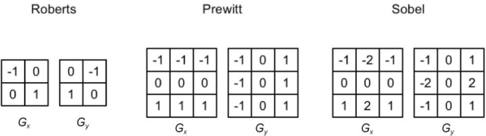
常用的边缘检测算子


在Unity中,屏幕后处理MonoBehaiver.OnRenderImage(RenderImage source,RenderImage destination)可以把屏幕上的渲染出来的图像传入到source中,再经过Graphics.Blit(source,destination,mat)方法指定一个材质处理后再渲染出来。
//脚本,挂载到Camera的物体上
using UnityEngine;

public class ImageChuliXia : MonoBehaviour {

    public Shader shader; //具体处理的Shader
    [Range(0, 3)]
    public float MingLiang = 1.5f;//明亮度
    [Range(0, 3)]
    public float BaoHe = 1.5f;//饱和度
    [Range(0, 3)]
    public float DuiBi = 1.5f;//对比度

    private Material mat;

    private void OnRenderImage(RenderTexture source, RenderTexture destination)
    {
        if (shader == null)
        {
            Graphics.Blit(source, destination);
            return;
        }

        if (mat == null)
        {
            mat = new Material(shader);//动态创建一个材质
            mat.hideFlags = HideFlags.DontSave;
        }

        mat.SetFloat("_Mingliang", MingLiang);
        mat.SetFloat("_Baohe", BaoHe);
        mat.SetFloat("_Duibi", DuiBi);
        Graphics.Blit(source,destination, mat);//直接调用方法,让mat处理一番
    }
}
//Shader处理
Shader "Unlit/ImageChuliXia"
{
Properties
{
_MainTex ("Texture", 2D) = "white" {} //这里会传入source
_Mingliang("_Mingliang",Float) = 1.5 //材质设置进来
_Baohe("_Baohe",Float) = 1.5
_Duibi("_Duibi",Float) = 1.5
}
SubShader
{
Tags { "RenderType"="Opaque" }
LOD 100
Pass
{
ZTest Always Cull Off
ZWrite Off
CGPROGRAM
#pragma vertex vert
#pragma fragment frag
#include "UnityCG.cginc"
struct v2f
{
float2 uv : TEXCOORD0;
float4 vertex : SV_POSITION;
};
sampler2D _MainTex;
float4 _MainTex_ST;
float _Mingliang;//明亮度值
float _Baohe;//饱和度值
float _Duibi;//对比度值
v2f vert (appdata_img v) //使用的内置的appdata_img
{
v2f o;
o.vertex = UnityObjectToClipPos(v.vertex);
o.uv = v.texcoord;
return o;
}
fixed4 frag (v2f i) : SV_Target
{
fixed4 renderTex = tex2D(_MainTex, i.uv);
//明亮度
fixed3 AllColor = renderTex.rgb * _Mingliang; //直接相乘就好了
//饱和度
//fixed lum = Luminance(renderTex.rgb); //计算当前颜色的亮度值
fixed lum = 0.2125 * renderTex.r + 0.7154 * renderTex.g + 0.0721 * renderTex.b;
fixed3 lumColor = fixed3(lum, lum, lum);//构建一个为0的饱和度
AllColor = lerp(lumColor,AllColor, _Baohe);
//对比度
fixed3 avgColor = fixed3(0.5, 0.5, 0.5);//构建一个为0的对比度
AllColor = lerp(avgColor, AllColor, _Duibi);
return fixed4(AllColor,renderTex.a);
}
ENDCG
}
}
Fallback Off
}appdata_img只包含图像处理时必需的顶点坐标和纹理坐标等变量。


如果说在有顶点动画的情况加,我们在常规的Pass修改了模型空间的坐标位置,如果还是使用内置的ShadowCaste去投射阴影的话就会产生错误,因为它用的还是没有修改过的模型顶点信息,所以这就需要自定义这个ShadowCaste的Pass了。
Pass {
	Tags { "LightMode" = "ShadowCaster" }

	CGPROGRAM

	#pragma vertex vert
	#pragma fragment frag

	#pragma multi_compile_shadowcaster

	#include "UnityCG.cginc"

	float _Magnitude;
	float _Frequency;
	float _InvWaveLength;
	float _Speed;

	struct v2f {
		//定义阴影投射的变量
		V2F_SHADOW_CASTER;
	};

	v2f vert(appdata_base v) {
		v2f o;

		//和常规Pass一样的顶点信息改变
		float4 offset;
		offset.yzw = float3(0.0, 0.0, 0.0);
		offset.x = sin(_Frequency * _Time.y + v.vertex.z * _InvWaveLength) * _Magnitude;
		v.vertex = v.vertex + offset;

		//直接使用定义好的宏去计算就好了,注意使用v,有vertex和normal
		TRANSFER_SHADOW_CASTER_NORMALOFFSET(o)

		return o;
	}

	fixed4 frag(v2f i) : SV_Target {
		SHADOW_CASTER_FRAGMENT(i) //定义好的宏
	}
	ENDCG
}
广告牌技术会根据视角方向来旋转一个被纹理着色的多边形(一般是一个简单的四边形,相当于广告牌),使得多边形看起来好像总是面对摄像机。本质是构建旋转矩阵,需要三个基向量。一般使用的基向量就是表面法线(normal)、指向上的方向(up)以及指向右的方向(right)。还需要一个锚点,这个锚点在旋转过程中是固定不变的,以此确定多边形在空间的位置。
Shader "Unlit/Bollboarding"
{
	Properties
	{
		_MainTex ("Texture", 2D) = "white" {}
	}
	SubShader
	{
		Tags { "RenderType"="Transparent" "Queue"="Transparent" "DisableBatching"="True" }
		LOD 100
		Cull Off
		Blend SrcAlpha OneMinusSrcAlpha

		Pass
		{
			CGPROGRAM
			#pragma vertex vert
			#pragma fragment frag

			#include "UnityCG.cginc"

			struct appdata
			{
				float4 vertex : POSITION;
				float2 uv : TEXCOORD0;
			};

			struct v2f
			{
				float2 uv : TEXCOORD0;
				float4 vertex : SV_POSITION;
			};

			sampler2D _MainTex;
			float4 _MainTex_ST;

			v2f vert (appdata v)
			{
				v2f o;
				fixed3 center = fixed3(0, 0, 0); //固定是原点
				fixed3 upDir = fixed3(0, 1, 0); //固定向上
				//中心指向摄像机,作为法线,就是被看见的面朝向摄像机
				fixed3 normalDir = normalize(mul(unity_WorldToObject, _WorldSpaceCameraPos)) - center;
				//算出新的右边的坐标轴
				fixed3 rightDir = normalize(cross(upDir, normalDir));
				//再算出真实上的坐标轴
				upDir = normalize(cross(normalDir, rightDir));

				//此时,center,normalDir,rightDir,upDir构建出了一个朝向摄像机的新模型空间在原模型空间的表示方式
				float3 offsetPos = v.vertex.xyz - center;
				float3 localPos = center + rightDir * offsetPos.x + upDir * offsetPos.y + normalDir * offsetPos.z;//变换到新的模型空间

				o.vertex = UnityObjectToClipPos(float4(localPos,1));
				o.uv = TRANSFORM_TEX(v.uv, _MainTex);
				return o;
			}

			fixed4 frag (v2f i) : SV_Target
			{
				fixed4 col = tex2D(_MainTex, i.uv);
				return col;
			}
			ENDCG
		}
	}
}
这里固定了一个向上的up,normal是根据相机视野来改变的,然后用这两个计算right,因为up和normal不一定是垂直的,所以up需要再使用right和normal叉乘计算。构建出坐标轴后对模型空间点进行变换方法可以查看 坐标空间变换过程坐标空间变换过程

效果


Shader "Unity Shaders Book/Chapter 11/Water" {
	Properties {
		_MainTex ("Main Tex", 2D) = "white" {} //水的贴图
		_Color ("Color Tint", Color) = (1, 1, 1, 1)
		_Magnitude ("Distortion Magnitude", Float) = 1 //幅度
 		_Frequency ("Distortion Frequency", Float) = 1 //频率
 		_InvWaveLength ("Distortion Inverse Wave Length", Float) = 10 //波段
 		_Speed ("Speed", Float) = 0.5  //贴图的uv速度
	}
	SubShader {
		//关闭Unity的动态合并网格,因为合并的话会破坏原模型空间
		Tags {"Queue"="Transparent" "IgnoreProjector"="True" "RenderType"="Transparent" "DisableBatching"="True"}

		Pass {
			Tags { "LightMode"="ForwardBase" }

			ZWrite Off
			Blend SrcAlpha OneMinusSrcAlpha
			Cull Off

			CGPROGRAM
			#pragma vertex vert
			#pragma fragment frag

			#include "UnityCG.cginc"

			sampler2D _MainTex;
			float4 _MainTex_ST;
			fixed4 _Color;
			float _Magnitude;
			float _Frequency;
			float _InvWaveLength;
			float _Speed;

			struct a2v {
				float4 vertex : POSITION;
				float4 texcoord : TEXCOORD0;
			};

			struct v2f {
				float4 pos : SV_POSITION;
				float2 uv : TEXCOORD0;
			};

			v2f vert(a2v v) {
				v2f o;

				float4 offset;  //顶点的偏移
				offset.yzw = float3(0.0, 0.0, 0.0);//除了x方向需要改变,其它都不用
				offset.x = sin(_Frequency * _Time.y+ v.vertex.z * _InvWaveLength) * _Magnitude;//这个看下面解释
				o.pos = mul(UNITY_MATRIX_MVP, v.vertex + offset);//在模型空间进行偏移后再转换到剪裁空间

				o.uv = TRANSFORM_TEX(v.texcoord, _MainTex);
				o.uv +=  float2(0.0, _Time.y * _Speed); //使用_Speed控制uv动画的速度

				return o;
			}

			fixed4 frag(v2f i) : SV_Target {
				fixed4 c = tex2D(_MainTex, i.uv);
				c.rgb *= _Color.rgb;

				return c;
			}

			ENDCG
		}
	}
	FallBack "Transparent/VertexLit"
}
Quad模型空间在x和z平面上
控制offset.x的偏移是sin(_Frequency * _Time.y+ v.vertex.z * _InvWaveLength) * _Magnitude
_Frequency和时间因子相乘,控制的是波动的速度
_InvWareLength和顶点的z轴相乘,z轴的范围在模型中是定好的,sin(z)的波段是固定的,所以加多一个_InvWareLength相乘后就可以控制波段了。
sin的范围是[-1,1] * _Magnititude就可以影响对x的影响了。

